Design Guide
- CNC -

PRINCIPALS OF CNC

CNC (Computer Numerical Control) Machining is one of the most common manufacturing and prototyping methods used in the manufacture of both metal and plastic parts.

This subtractive manufacturing technology is based on a block of raw material which is subjected to a machining controlled material-removal process using cutting tools in successive phases until the final geometry of the desired part is achieved.

Machining is the technique which allows to achieve the highest quality parts (compared to 3D printing). Practically any type of material can be machined, both metallic (among others, aluminium or magnesium alloys, steels) and plastic (such as ABS, Nylon, Delrin, etc..).

Even if many geometries can be programmed manually, Proto&Go! always requires a 3D CAD file to program the CNC machines using a CAM software, which guarantees the accuracy of the result and avoids possible errors in drawings or versions.

PROCESS

Starting from the 3D file, the file of the part to be manufactured is processed by a CAM (“computer assisted manufacturing”) software from which toolpaths to be manufactured are determined based on the geometry of the part.

From these virtual toolpaths obtained by the CAM software, a machine code is generated that indicates to the control panel of the machine all the parameters and conditions required to manufacture the part: tool rotation speed, spindle feed speed, depth of each pass, type of tool, etc.

In general, for most parts, the intervention of different tools is required, each with its own particularities, which are used successively in different machining phases until the final geometry is achieved.

TYPES OF CNC MACHINERY

Among other characteristics, machining machinery is classified according to the number of axes with which they can work, usually referring to 3, 4 or 5 axes.

There are machines with more working axes or other configurations, as well as machines dedicated to laser cutting, waterjet cutting or EDM. This guide, however, limits its focus to CNC machines that work with cutting tools.

CNC MILLING - 3 AXIS

The most common 3-axis CNC machines include both CNC milling machines and CNC turning machines.

With this type of machine, the cutting tool can move in three linear axes, X, Y, Z (and/or in between interpolations) in line with the workpiece.

In milling machines, the block of material is static and the tools are rotating in order to achieve cutting speed and to be able to remove material.

In the case of a milled part, the resulting geometry can be any geometry, and should not be limited only to revolution parts as it is the case with turning machines.

The first 3 axes allow a relative movement between tool and material on an X, Y, Z coordinate axis.

This is the most common and popular type of milling machine.

CNC MILLING - 4 AXIS

To give the CNC milling machine more flexibility when positioning a part with respect to its axial axis, an electromechanical module with a 4th axis can be integrated to give the machining centre an additional degree of rotation.

This operation is normally performed by adding this 4th axis module to a conventional 3-axis machine.

CNC MILLING - 5 AXIS

The machining centres with  5 axes have either a motorised bed or the spindle itself has two extra levels of flexibility in addition to the original 3 axes.

Generally, 5-axis machines are more versatile in the whole machining process, but their acquisition cost is considerably higher, so that the parts processed on this type of machine are generally more expensive.

CNC TURNING - 3 AXIS

The most obvious feature on the turning machine (lathe) is that the raw material rotates on itself in the spindle and the tools impact on it, generating the machining removal paths.. The result is a so-called “turned” part.

Generally, turned parts are more economical than parts requiring milling because the process is quicker and easier to automatize. Therefore, turning is a process with which high production rates can be achieved at low cost, as long as a revolution part is designed.

CNC TURNING - 4 AXIS

The most obvious feature on the turning machine (lathe) is that the raw material rotates on itself in the spindle and the tools impact on it, generating the machining removal paths.. The result is a so-called “turned” part.

Generally, turned parts are more economical than parts requiring milling because the process is quicker and easier to automatize. Therefore, turning is a process with which high production rates can be achieved at low cost, as long as a revolution part is designed.

MANUFACTURABILITY

ost of the parameters, such as machining strategy, cutting speed, tool type or depth of cut, are defined on the machine shop floor, but there are some details that can be done during the product design phase, not only to ensure manufacturability but also to obtain parts that are more economical and easier to industrialise.

Here are some of the most important points to take into consideration when designing a part and optimising its cost.

INTERNAL EDGES

Characteristic

The tools used to machine the internal recesses have a cylindrical shape, so it is not possible to obtain edges with a radius of 0 in the internal cutouts.

Rule for the design

  • The recommended minimum radius to be applied to an internal edge will depend on the height of the cutout itself, with a radius of more than 1/3 of the depth being considered a reasonable value.
    The bigger the radius applied,
    the easier it is to produce, and therefore, the lower the cost.
  • In any case, avoid radii smaller than 1 mm.

Recommendations

  • In case the internal cut-out has to enclose another part where the wall-to-wall fit is important, the option of tooling outlets on the inner radii is recommended.
  • An alternative and also optimal solution is to make external chamfers on the part that is placed inside the cut-out.

THREADS

Characteristic

Tools for making internal threads, thread taps, are a fragile element with limited length, so it is important to evaluate during the design process the best way to plan the threaded holes in order to minimise the manufacturing cost.

Rules for the design

  • The thread depth is defined according to the nominal thread diameter. Depths more than
    3 x nominal thread diameter are generally not necessary.
  • To be able to make a thread, the hole must be drawn in the 3D file and must have a diameter equivalent to the nominal diameter of the thread minus 1x pitch.
  • The threading of a hole requires a thread free space at the bottom of the hole, which must be at least 3 times the pitch.
  • It is recommended to design threaded holes from M3 or more.
  • Threads smaller than M2 are not achievable.

Recommendations

  • Deep threads are not recommended. If the thread is to be used at both ends, it is advisable to make the thread at both ends of the drill hole.
  • Whenever possible, it is more practical, and more economical, to tap through holes rather than blind holes.
With your next order at Proto&Go! you will receive our useful scale for the design of screw joints.

UNDERCUTS

Characteristic

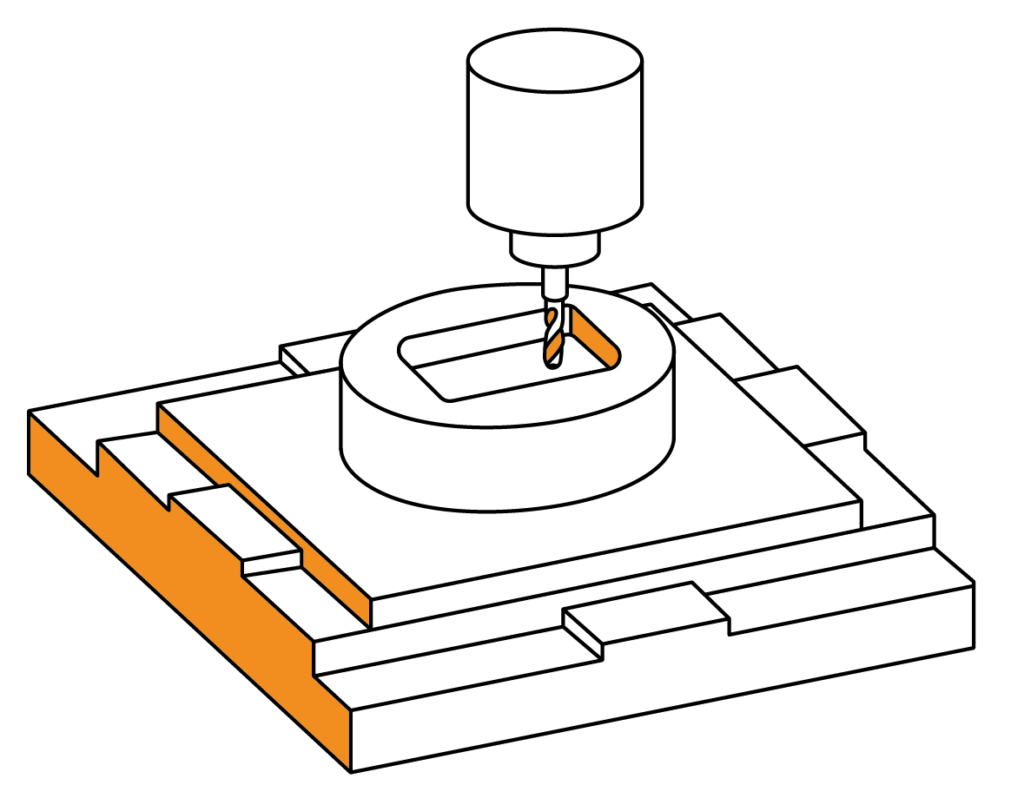
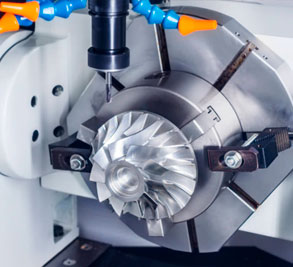
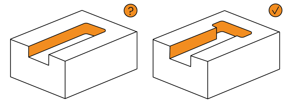
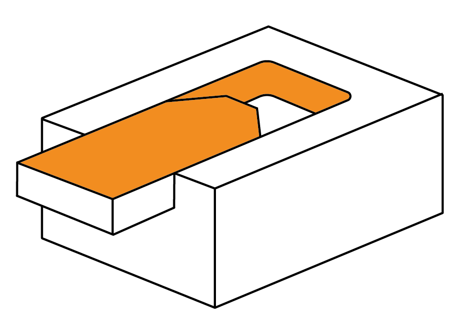
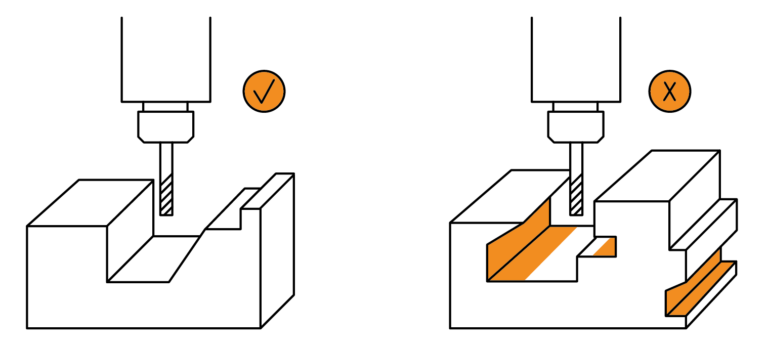
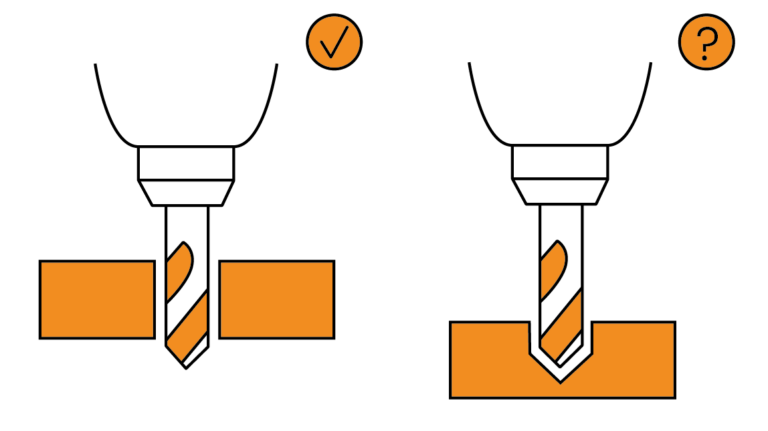
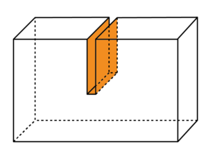
Undercuts are sections in the design where it is geometrically impossible for a standard CNC machining tool to access.

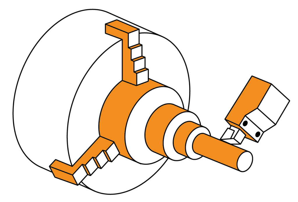
Due to the shape of the tools themselves, generally cylindrical, there are certain geometries in the designed parts that may not be achievable, leading to so-called undercuts.

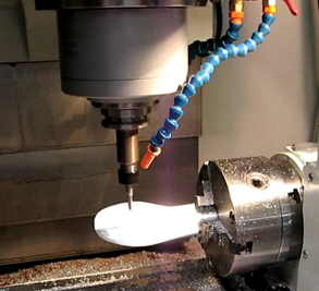
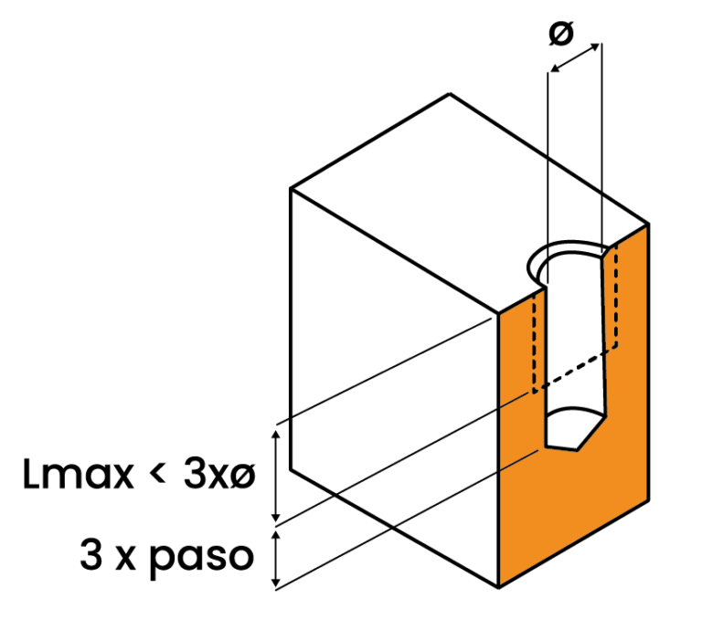
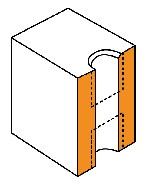
There are some exceptions such as inverted T-sections for which tooling is available, but in general, in order to produce a negative, either special purpose-made tools or post-machining processes are required.

Rule for the design

  • Avoid creating negatives in the design of the parts.

Recommendations

  • To avoid designs with undercuts, it is recommended to make the required design in two separate parts which can be joined together afterwards.

DRILLING

Characteristic

Tools for making internal threads, taps, are a fragile element with limited lengths, so it is important to assess during the design the best way to approach the threaded holes in order to minimise the manufacturing cost.

Rules for the design

  • Blind holes have a conical bottom. This must be taken into account in the design.
  • Recommended drilling depth: less than 4 x nominal diameter.
  • Maximum depth that can be manufactured: 10 x nominal diameter.
  • Minimum recommended diameter: Ø2.5
  • Minimum manufacturable diameter is Ø0.5.

Recommendations

  • Whenever possible it is more interesting to drill through holes rather than blind holes.
  • It is recommended to use standard drilling diameters (Ø6, Ø7,5, Ø10,…) and very specific sizes that require custom-made tolos (Ø6,57) should be avoided.

THICKNESSES

Characteristic

During the machining process, cutting tools are not only heated to very high temperatures but also generate a high level of vibration. As a result, particularly thin walls can break or become deformed.

Rules for the design

  • Recommended mínimum thickness:
    • Plastics: 1,5 mm.
    • Metals: 0,8 mm.

SLOTS

Characteristic

For the design of slots it is important to take into consideration the width-depth range, as the cutting tools have a limited length.

Rules for the design

  • Maximum Depth:
    • 15 x diameter for plastics.
    • 10 x diameter for aluminium.
    • 5 x diameter for steels.

CUT & GLUED / WELDED

Characteristic

Due to the properties of certain materials and the geometry required in the design, it is possible to realise the design in several parts, which afterwards are glued (plastics) or welded (metals). This simplifies and optimises the manufacturing process.

This procedure is usually applied on ABS plastic material because its properties make it suitable for the construction of very complex aesthetic prototypes.

It is also possible to propose the use of a welded joint in certain designs of aluminium parts which, due to their geometry, cannot be manufactured from a single block.

Note for clarification:

During the purchasing process on our online platform you will be clearly informed about our proposal to use a glued or welded joint for the construction of your part.

TOLERANCES

General Tolerances

Tolerance is the acceptable range of tolerance specified by the designer for a dimension which ensures the functionality of the part in terms of its shape, fit and use.

In case the quotation does not include a 2D drawing with a specific tolerance request, Proto&Go! will manufacture the parts according to ISO 2768fH for metals and ISO 2768mK for plastics:

Specific Tolerances

In the case where, due to the functionality of the part, the general tolerances are not sufficient, the designer or engineer has to indicate the required tolerances on a drawing.

It is important to point out that the stricter the tolerances are, the higher the manufacturing cost of the part is, up to double the cost it would have with standard tolerances.

If there are specific geometrical tolerances or any type of specification that must be respected, these can also be indicated on the enclosed drawing.

To minimise the manufacturing cost, it is recommended to use specific tolerances only in really critical areas.

Restrictions

Proto&Go! can only guarantee dimensional tolerances above IT7 (H7, g8, P9, …) as well as surface roughness above Ra 1.6.

More restrictive values require subsequent machining processes after CNC machining.

If you have further questions, please do not hesitate to contact the Proto&Go! support department via:

info@protoandgo.com | (+44) 20 3318 1736

or via our online chat system.