Design Guide
- 3D Printing -
BASICS OF 3D PRINTING
3D printing refers to the different procedures by which the physical construction of a 3D design can be achieved by additive manufacturing.
Differently to CNC machining, where the part is obtained from the subtraction of material from a starting block, in additive manufacturing, the geometry is obtained from the solidification of the starting material layer by layer.
Traditionally, this technique is more common for plastic materials, even if metal and other materials are becoming more and more popular.
ADVANTAGES OF 3D PRINTING
Fast delivery times
Parts are normally shipped in only 5 days, which allows faster design iterations and quicker market launch.
Complex geometries
Practically any geometry, no matter how complex, can be achieved without the limitations of other production processes.
Cost
Being a high and easy to produce technology, the costs to obtain parts are generally lower than any other technology, making it the ideal choice for pre-prototyping and rapid product testing.
Scalability
With the Proto&Go! 3D printing, a single part or component can be produced as easily as several dozen production parts without the need for investment in tooling or moulds.
Durability
3D printing can offer high impact resistance, medium flexibility and high resistance to environmental factors.
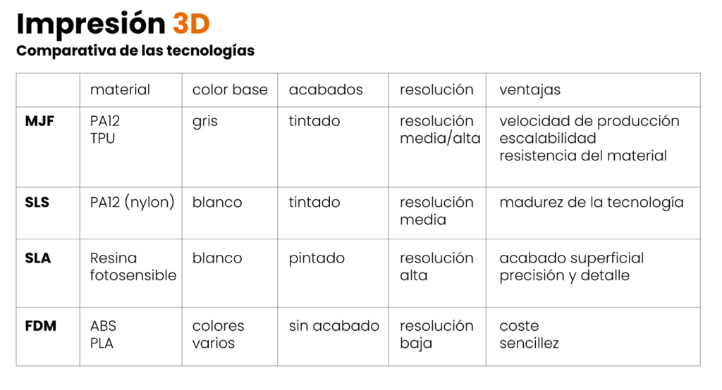
ADVANTAGES OF 3D PRINTING
MJF – Multijet Fusion by HP
This is the latest and most advanced industrial printing technology, which is why it is the one chosen by Proto&Go! for your projects.
This machine has been developed by HP to obtain both prototypes and series of parts in materials such as Nylon – PA12 or flexible TPU, among others.
The manufacturing speed and the resistance of the resulting parts are remarkable. Therefore, 100% functional parts can be obtained in just a few days and with a high resolution.
SLA – Stereolithography
Stereolithography belongs to a family of additive manufacturing technologies known as photopolymerisation, or commonly, resin 3D printing. The main concept of this technique is the use of a light source (a laser) to harden liquid resin and transform it into solid plastic.
Parts made using SLA offer the highest resolution and accuracy, the sharpest details and the smoothest surface finish of all 3D printing technologies, making it ideal for aesthetic parts.
On the other hand, they have a disadvantage in that, as the material is photosensitive, the pieces obtained do not withstand the passage of time or exposure to ambient light and are generally fragile for small cross-sections.
For this reason, we, at Proto&Go!, prefer to opt for CNC machining of ABS to obtain parts for aesthetic purposes such as housings or fairings.
SLS – Selective Laser Sintering
It is a well established technology with which parts in Nylon, Polypropylene or other materials can be obtained by fusing powdered material by applying heat with a single-point laser.
SLS is a pre-MJF technology with similar characteristics but without some of its advantages, such as material isotropy and manufacturing time.
FDM – Fused Deposition Modelling
This technique is often considered the most simple method existing. Fused Deposition Modelling or FDM technology is based on 3 main elements: a printing bed/plate on which the part is printed, a spool of filament that serves as the printing material and an extruder. In summary, the filament is melted by the 3D printer’s extruder, which deposits the material accurately layer by layer on the print bed.
The most common materials for this type of printing, among others, are ABS and PLA.
The big advantage of this technique is its simplicity and economy, making it the technology most widely used in the domestic sector.
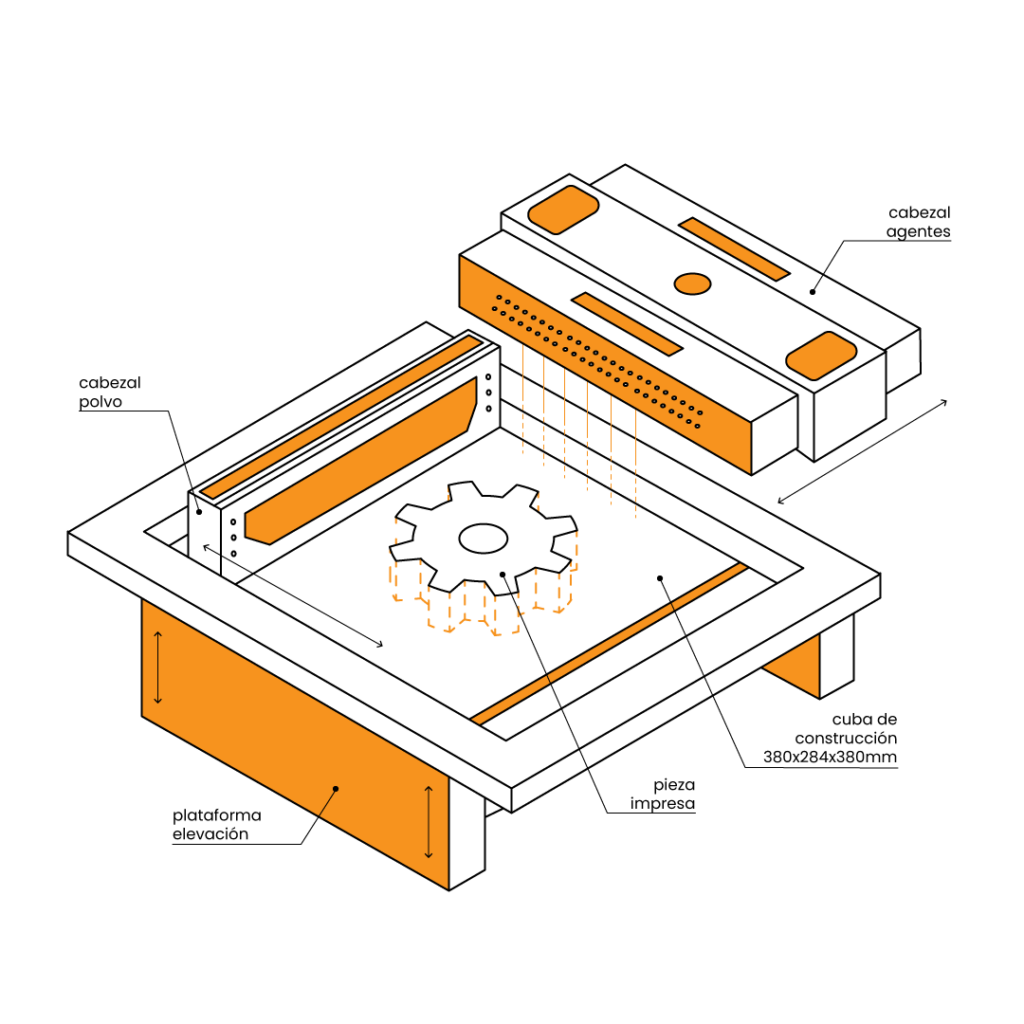
PROCESS - MULTIJET FUSION (MJF)
The process starts with a coating head that deposits a very thin layer (typically 0.08 mm) of the powder material, PA12 or TPA, on the construction platform. After the deposition of a first layer, a second moving head applies the agents on the part geometry that will delimit the area to be sintered by a melting unit incorporated in the head itself.
Once the entire cross-section has been scanned, the construction platform lowers a layer thickness in height. The unsintered powder remains in place to support subsequent layers, eliminating the need for support structures..
The coating head deposits a new layer of powder on top of the previous, already sintered layer, and the head with the agents and the melter makes a new run to sinter the new section on top of the previously solidified ones. This process is repeated until all the parts are completely manufactured.
The result is a container full of powder and solidified parts that must be left to cool for at least 24 hours before being removed.
CHARACTERISTICS - MULTIJET FUSION (MJF)

APPLICATIONS - MULTIJET FUSION (MJF)
Parts produced by MultiJet Fusion printing are commonly used industrially for rapid prototyping and full production runs:
- aerospace
- automotive
- commercial products
- industrial products such as special machinery
- medical care
MFJ functional parts and prototypes are used for:
- drones
- robotics
- special machinery
- ioT devices
- sports equipment
- footwear
- orthopaedic technology
- education
- medical devices
MultiJet Fusion 3D printing (MJF) is also a good technology for creating detailed architectural models at a reasonable cost.
DESIGN RECOMMENDATIONS
Most of the parameters required for the printing strategy, such as the position and orientation of the parts in the printing bed among others, are defined directly by the 3D printing technicians to optimise the results. Nevertheless, during the product development phase, designers and engineers may also have considerations to ensure the manufacturability of the part and to obtain parts that are more economical and easier to industrialise.
We have listed some of the best practices to consider when designing a part to optimise its cost.
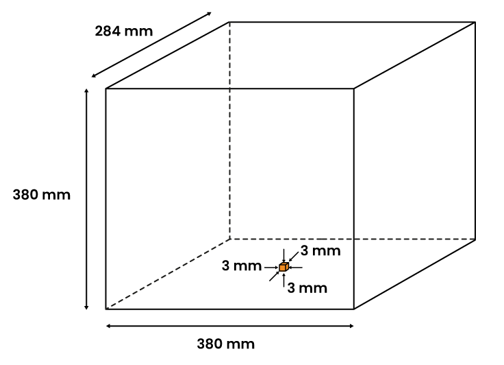
DIMENSIONS
Characteristic
The Multi Jet Fusion printer has a maximum box size of 380 x 284 x 380, therefore this is the maximum part size that can be produced.
Design rules
- Maximum manufacturable part size: 380 x 284 x 380 mm.
- Minimum manufacturable part size: 3 x 3 x 3 mm.
TOLERANCES
Characteristic
As in any production process, in 3D printing there are also tolerances to be taken into account before designing parts that need to be adjusted.
Design rules
Dimensional tolerance: ± 0,3% of nominal dimension with a minimum of ± 0,3 mm.
- If the dimension is less than 100 mm. the expected tolerance is ± 0,3 mm.
- If the dimension is bigger than 100 mm. the expected tolerance is ± 0,3%of the original dimension.
Examples

MINIMUM THICKNESS
Characteristic
The high temperatures generated during powder sintering can lead to deformation or breakage of very thin walls. Therefore, there is a minimum value which cannot be exceeded in order to avoid construction defects.
Design rules
- Minimum manufacturable thickness: 0,5 mm
- Recommended minimum thickness: 0.8 mm
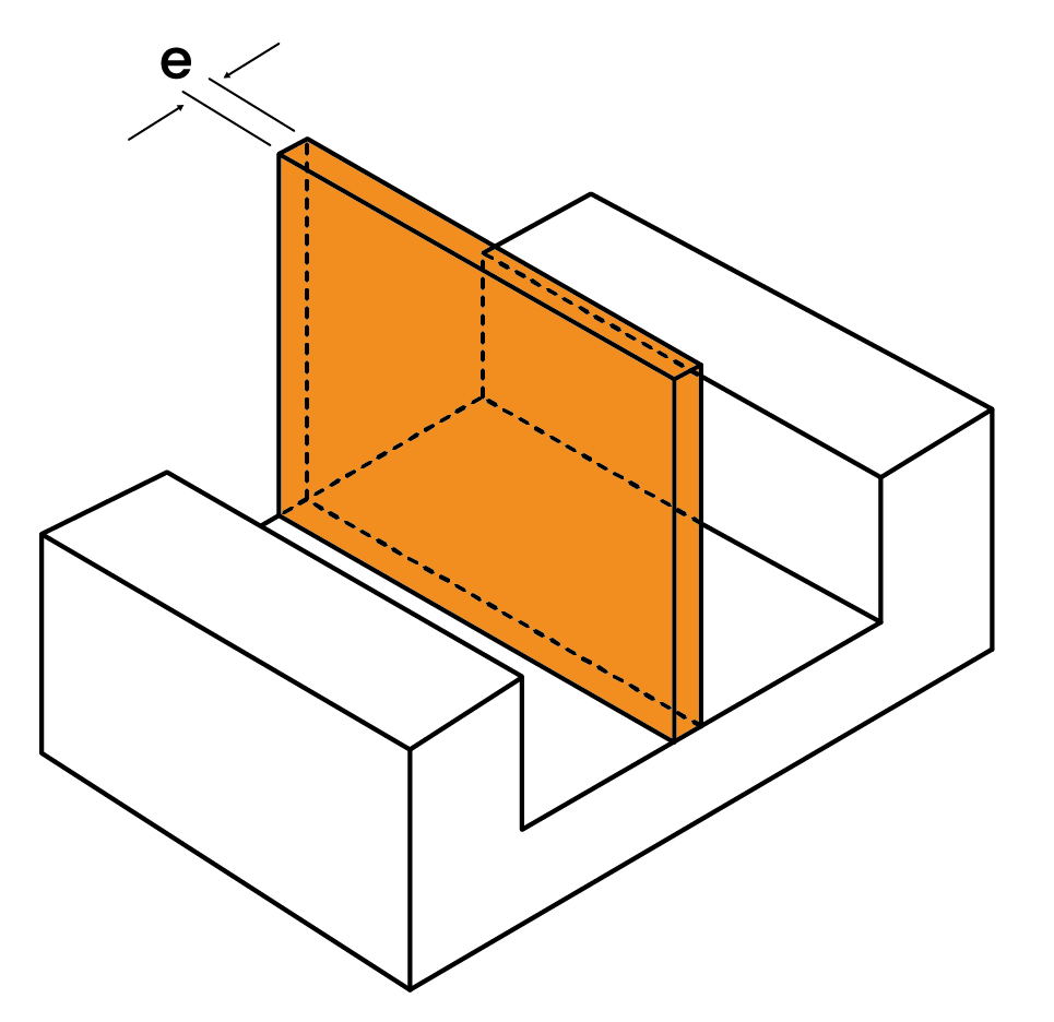
Recommendations
If tight walls (high and thin) or thin walls are required, we recommend ripping the wall or using support walls.
MAXIMUM THICKNESS
Characteristic
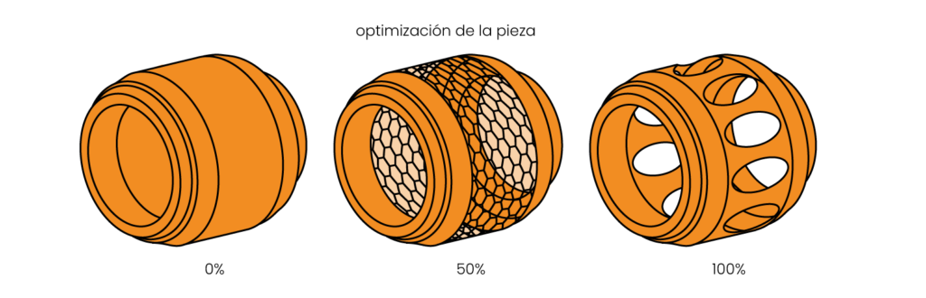
Powder fusion at high volume densities is not possible due to the concentration of temperatures inside the part. In addition, in 3D printing the main cost is given by the amount of powder contained in the part.
For both reasons it is recommended to avoid designs with wall thicknesses which are too big.
Design rule
Maximum recommended thickness:
- For PA12 – 10 mm
- For TPU – 6 mm
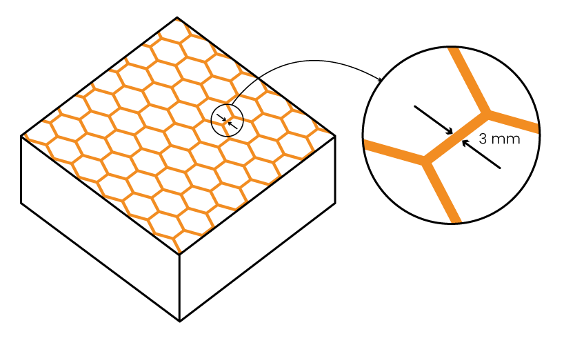
Note:
In case of requiring a thickness above the recommended thickness when printing the part, it will be done automatically with an “infill” (inner bee panel) with 3mm thick walls and holes which allow escape of the dust lodged in the interior. You can also choose to remove the entire wall and leave the bee panel visible.
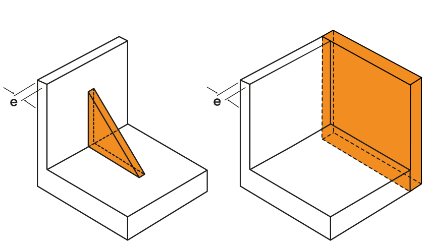
Recommendation
Design a part that incorporates structural elements that provide rigidity while minimising thicknesses.
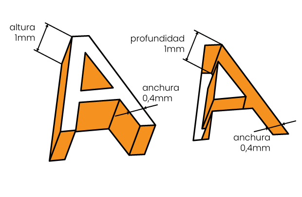
LETTERS OR LOGOS
Characteristic
La tecnología Multi Jet Fusion permite imprimir letras y/o dibujos con una resolución y definición muy altas.
Design rule
- Minimum printable font: 6 point
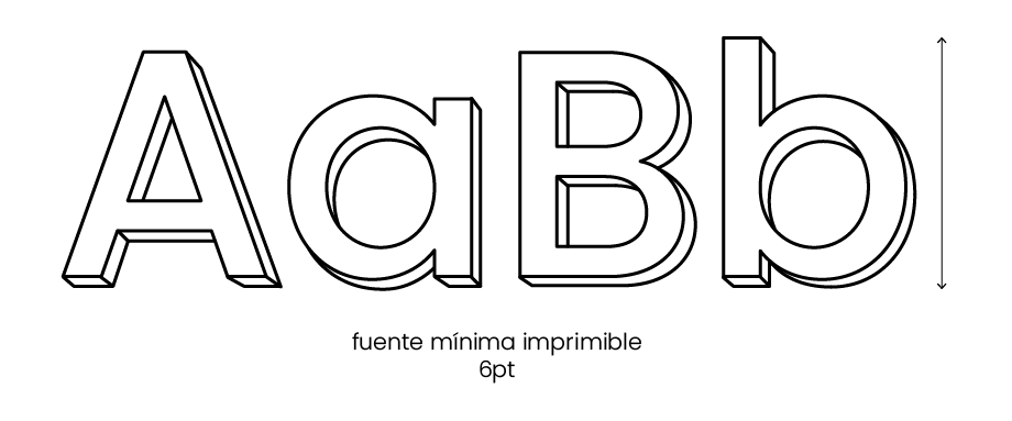
- Minimum letter height or depth: 1 mm
- Minimum letter width: 0,4 mm
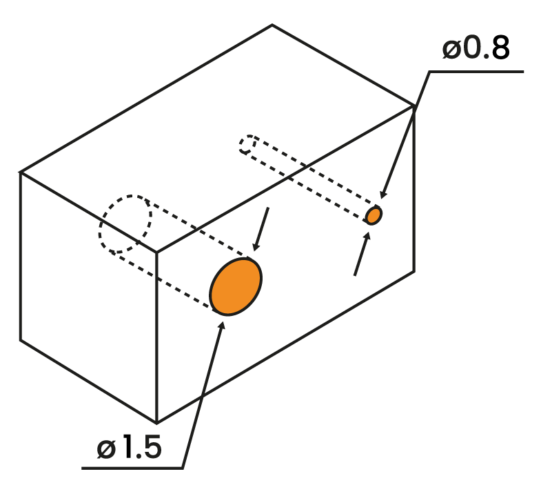
HOLES
Design rule
- Minimum recommended diameter: 1.5 mm
- Minimum manufacturable diameter: 0.8 mm
THREADS/INSERTS
Characteristic
Threads with diameters larger than M5 are printable and functional using the Multi Jet Fusion technology.
It is also possible to fit metal inserts.
Recommendation
To avoid threading problems, it is recommended to design the threads with a tolerance of 0.2 mm in diameter.
In this way, if you want to obtain a threaded shaft of M6, whose outside diameter should be Ø6, our recommendation is to reduce this outside diameter to Ø5.8 to avoid tolerance problems when threading.
In the case of a threaded hole, nut or socket, the tolerance must be positive, making the diameter larger than it should be originally.
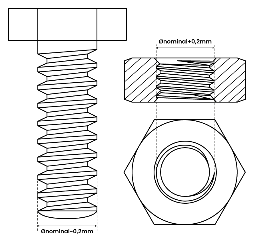
- Screw: Øoutside = Ønominal – 0,2 mm.
- Nut: Øinside = Ønominal + 0,2 mm.
Note:
For threads from M3 to M8, metal inserts are the best solution for the implementation of threads in a printed part.
If you have further questions, please do not hesitate to contact the Proto&Go! support department via:
info@protoandgo.com | (+44) 20 3318 1736
or via our online chat system.