There comes a point when a part is no longer difficult to machine because of its shape, but rather because of its thickness. This happens with lightweight housings, heat sinks, and any design in which material has been removed to save weight: the geometry is simple, but the wall is so thin that it vibrates as soon as the milling cutter touches it.
This phenomenon has a name—chatter—and it’s what sets the actual limit for thin walls in machining. It’s not a matter of whether or not the machine can reach that depth; it’s that the workpiece moves while it’s being cut. In this article, we’ll look at the thickness at which the problem begins, what rule really applies, and how to design to avoid it.
Why Does a Thin Wall Vibrate During Machining?
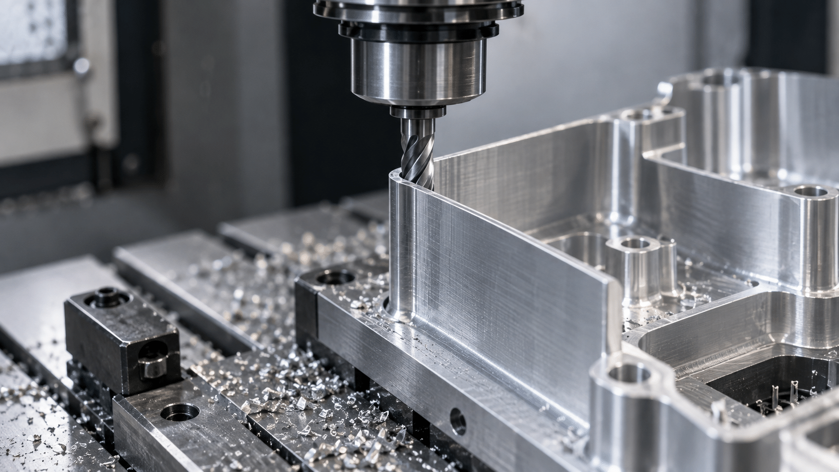
As it is machined, the wall behaves like a cantilever beam: it is supported at the base and unsupported at the top. The milling cutter pushes sideways; the wall shifts, returns to its original position, and shifts again. This oscillation feeds back as the tool’s teeth pass over it, eventually resulting in sustained vibration.
The key is that stiffness does not drop in proportion to thickness, but much faster: it is proportional to the cube of the thickness. Put the other way round, taking a wall from 1 to 2 millimetres does not make it twice as rigid, it makes it eight times more rigid. That is why half a millimetre more in the design completely changes how the part behaves on the machine.
Recommended minimum thickness by material
As a starting point for CNC machining, these are the thicknesses that can be worked with confidence:
| Equipment | Minimum requirements | Recommended | Comments |
|---|---|---|---|
| Aluminum | 0.8 mm | 1.5 mm | The most versatile: rigid and easy to cut |
| Stainless steel | 0.8 mm | 1.5 – 3.0 mm | High cutting forces: increased vibration and thermal deformation |
| Carbon steel | 0.8 mm | 1.5 – 3.0 mm | Same as stainless steel; also be careful with stresses |
| POM / Delrin | 1.5 mm | 2.5 mm | Yields under the tool and recovers: unstable dimension |
| PA / Nylon | 1.5 mm | 3.0 mm | Absorbs moisture and warps after machining |
It is noteworthy that plastics allow for thinner walls than metals. The reason is that the material must not only withstand the cutting process but also maintain its dimensions afterward. A 1-millimeter-thick piece of nylon moves away from the cutter, returns, and ends up with a thickness different from what was specified.
The height-to-thickness ratio: the rule that really matters
Thickness alone doesn’t tell us anything. A wall that is 1 millimeter thick and 5 millimeters high poses no problem; that same wall, if it were 60 millimeters high, would be impossible. What sets the limit is the ratio of clear height to thickness:
- Up to 10:1 — safe range. Can be machined without special precautions.
- Between 10:1 and 15:1 — requires special measures: lighter passes, support tools, or multi-stage machining. This increases machining time and cost.
- Above 15:1—that’s the limit for a wall without support. Beyond that, you have to redesign or change the process.
For plastic, it’s best to divide those values by two. And this rule applies equally to ribs and flanges, not just to the outer walls.
What happens when the wall is too thin?
The problem isn’t that the part doesn’t come out; it’s how it comes out. The symptoms are always the same:
- Vibration marks that no subsequent finishing process can completely remove.
- Irregular thickness, with the dimension outside the specified tolerance.
- The wall bulges when the fastener is released, due to the release of tension.
- More machine time and, consequently, a higher price.
How to Design a Thin Wall That Can Be Machined
There’s almost always some leeway with the CAD before asking the shop to work a miracle:
- Increase the thickness where it can’t be seen. It is rarely necessary for the wall to be thin across its entire surface; it is sufficient for it to be thin in the functional area.
- Add veins or eyelashes. A transverse rib every few centimeters radically changes the behavior of the wall without adding much weight.
- Make the base with a generous radius. That is where the force is concentrated and where the wall breaks or opens up.
- It reduces the headroom. Dividing a tall wall with an intermediate step improves the height-to-thickness ratio without changing the thickness.
- Avoid thin, opposing walls. Two thin, parallel walls vibrate against each other, making the problem worse.
These are the criteria outlined in the article on wall thickness and the one on design for manufacturability: ten minutes in CAD that save days on the shop floor.
What Can the Workshop Do When the Wall Is Inevitable?
If the design does not allow for changes, there are still options available: machining in stages while leaving support material that is removed at the end, fabricating a jig to support the wall, machining with shallow cuts and high speed, or alternating between machining on both sides.
It works, but it takes machine time and preparation. It’s better to know this before ordering the part than after—that’s the kind of detail we go over from CAD to the shop floor.
Machine your parts with PROTO&GO!
At PROTO&GO!, we manufacture parts made of aluminum, stainless steel, carbon steel, POM, and nylon with delivery in 8 business days. When you upload your file, you’ll receive a feasibility analysis within a few hours: if any wall thickness is below the acceptable limit, we’ll let you know before manufacturing and suggest an alternative.
Get a quote for your pieces now and clear up any doubts about your design.