How to avoid warping in 3D printing and CNC.
On screen, everything seems solid. On the workbench, a poorly dimensioned wall can warp, crack, vibrate during manufacturing, or cause the part not to fit.
When designing a part, it is easy to obsess over the shape and critical dimensions and assume that the walls «will hold up». But wall thickness is one of the parameters that most determines whether a prototype will come out straight and strong or if the dreaded warping appears: that deformation that curves, twists, or lifts the part.
At Proto&Go! we manufacture parts using 3D printing, CNC machining and silicone molds, and a large part of the deformation problems can be reduced by correctly controlling the wall thickness.
What is wall thickness and why does it cause warping?
Wall thickness is the material thickness between two surfaces of a part. Although it may seem like a minor detail, it directly conditions strength, weight, cost, and, above all, dimensional stability.
In 3D printing and molded parts, warping occurs mainly when different zones of the part cool or contract at different rates. A very thin wall can deform or lose rigidity, while an excessively thick section can accumulate heat and contract unevenly.
In CNC machining, the causes are different. Walls that are too thin can flex or vibrate due to cutting forces. Additionally, the part can deform when material is removed and internal stresses present in the original block are released.
The result can be the same: raised edges, wavy surfaces, dimensional deviations, or parts that lose their flatness. The key is not just «putting enough material», but distributing it intelligently and adapting it to the manufacturing process.
The golden rule: maintain a uniform thickness
Maintain consistent thicknesses and avoid abrupt section changes.
Sudden changes in thickness, such as a solid zone next to a thin wall, can generate uneven cooling, stress concentrations, and different behaviors during manufacturing.
To avoid it:
- Design walls with the most constant thickness possible, as long as the part's function allows it.
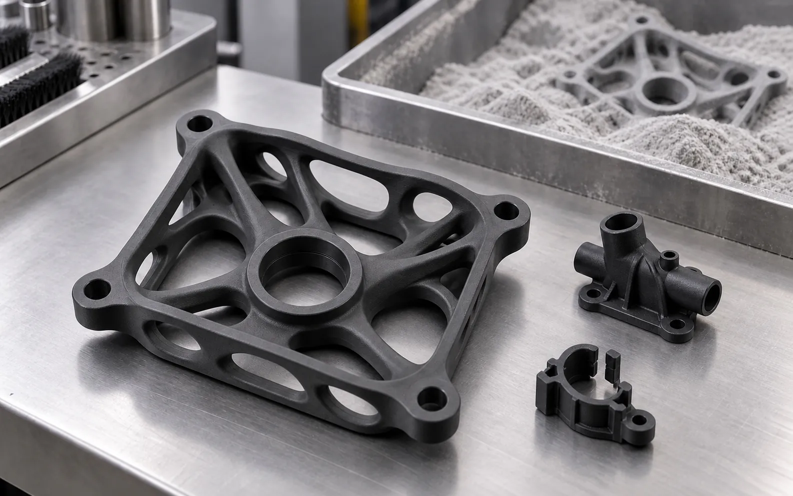
- In printed or molded parts, hollow out unnecessary solid zones to reduce material, cost, and risk of uneven contraction.
- In CNC machining, remove material in a balanced way and maintain sufficient rigidity throughout the process.
- If you need to increase rigidity, use reinforcing ribs instead of thickening the entire wall.
This rule is especially important in 3D printing and molded parts. In machining it also helps, although other factors such as wall height, clamping, material, and cutting strategy must be taken into account.
Recommended minimum wall thicknesses by technology
There is no single value: each technology and material has its own limits. These values are initial references and must be adapted to the part's size, geometry, and application.
- FDM: Around 1 or 1.2 mm is usually a good starting point for functional parts. The value will depend on the nozzle diameter, the number of perimeters, the material, and the print orientation.
- SLA / photopolymers: Approximately 0.8 mm can be used as a reference for functional walls. Thinner thicknesses can be manufactured, but they may be more fragile and sensitive to orientation, supports, and post-curing.
- SLS with PA12: Between 0.8 and 1 mm usually provides a good balance between strength and lightness, although certain geometries can be manufactured with thinner walls.
- MJF with PA12: It is advisable to start with approximately 1 to 2 mm and validate the design according to size, geometry, and mechanical requirements.
- CNC machining: As a general reference, it is advisable to avoid walls thinner than 0.8 mm in metal and 1.5 mm in plastic, especially if they are tall, long, or poorly supported. In certain geometries and materials, thinner thicknesses can be machined, but the risk of vibration, deflection, and deformation increases.
As a practical reference, a range of 1.5 to 3 mm works well for many plastic housings and prototypes. It is also not advisable to over-dimension walls in 3D printed or injection molded plastic parts: very thick sections can cool and shrink unevenly.
Ribs and fillets: stiffness without thickening
When a part needs to withstand loads, the temptation is often to thicken the wall. However, adding material over the entire surface is not always the best solution.
- Use reinforcing ribs to increase stiffness without excessively increasing weight or material volume.
- For thermoplastic injection molding parts, ribs are typically designed with a thickness between 50% and 60% of the nominal wall thickness. This proportion helps reduce the risk of shrinkage voids or sink marks.
- In 3D printing, CNC machining, and silicone molds, rib thickness must be defined according to the technology, material, geometry, and loads the part must withstand.
- Replace sharp corners with radii and fillets. Radii distribute stresses better, improve flow in molded parts, and reduce points where cracks can initiate.
- Design smooth transitions between areas of different thickness instead of abrupt steps.
Other tips to minimize warping
Beyond thickness, there are other factors that help the part stay straight:
- Orientation: how the part is placed in the machine affects how it is manufactured, cooled, and deformed.
- Material: ABS tends to warp more than PLA or PETG. PA12 from MJF and SLS usually offers good dimensional stability, although it can also deform on large surfaces or unbalanced geometries. Compare in ABS, PA12, or aluminum.
- Large flat surfaces: are especially prone to warping. You can divide them, add ribs, introduce a slight curvature, or modify the manufacturing orientation.
- Fixturing and machining: in CNC, inadequate fixturing or excessive cutting forces can deform a thin wall. The machining strategy must maintain part stiffness throughout the process.
- Realistic tolerances: do not over-tighten non-critical areas. Unnecessarily tight tolerances increase cost and rejection risk. Check them with the tolerance calculator.
Wall thickness is a perfect example of why design for manufacturability (DFM) makes a difference: a small adjustment to the 3D model can avoid rework, breakage, and deformed parts.