Engineering resources

Measure, choose, and calculate. Before requesting a quote.

Open your STEP, measure it, choose process and material, calculate ISO 286 tolerances and fits, and download the design guides. Free and no registration required.

01 / 3D viewer

Open your part.
Measure it and analyze it.

STEP, STL or OBJ in the browser, without installing anything. Drop the file on the image and it opens in the viewer. With one click, the manufacturability check tells you whether it can be machined.

STEP · STP · STL · OBJ

STEP viewer and manufacturability check (DFM)

Rotate the part, measure edges and diameters, see what it weighs in the material you choose and check whether it can be machined.

  • Exact STEP measurements: diameters, radii and distances
  • Bounding box, volume, surface area, and weight
  • Warns about multiple parts and open surfaces
  • Manufacturability check (DFM): radii, walls, holes and areas with no access
  • No registration, and your file isn't stored
02 / Manufacturability check (DFM)

Can your part be machined?
Check it for free before requesting a quote.

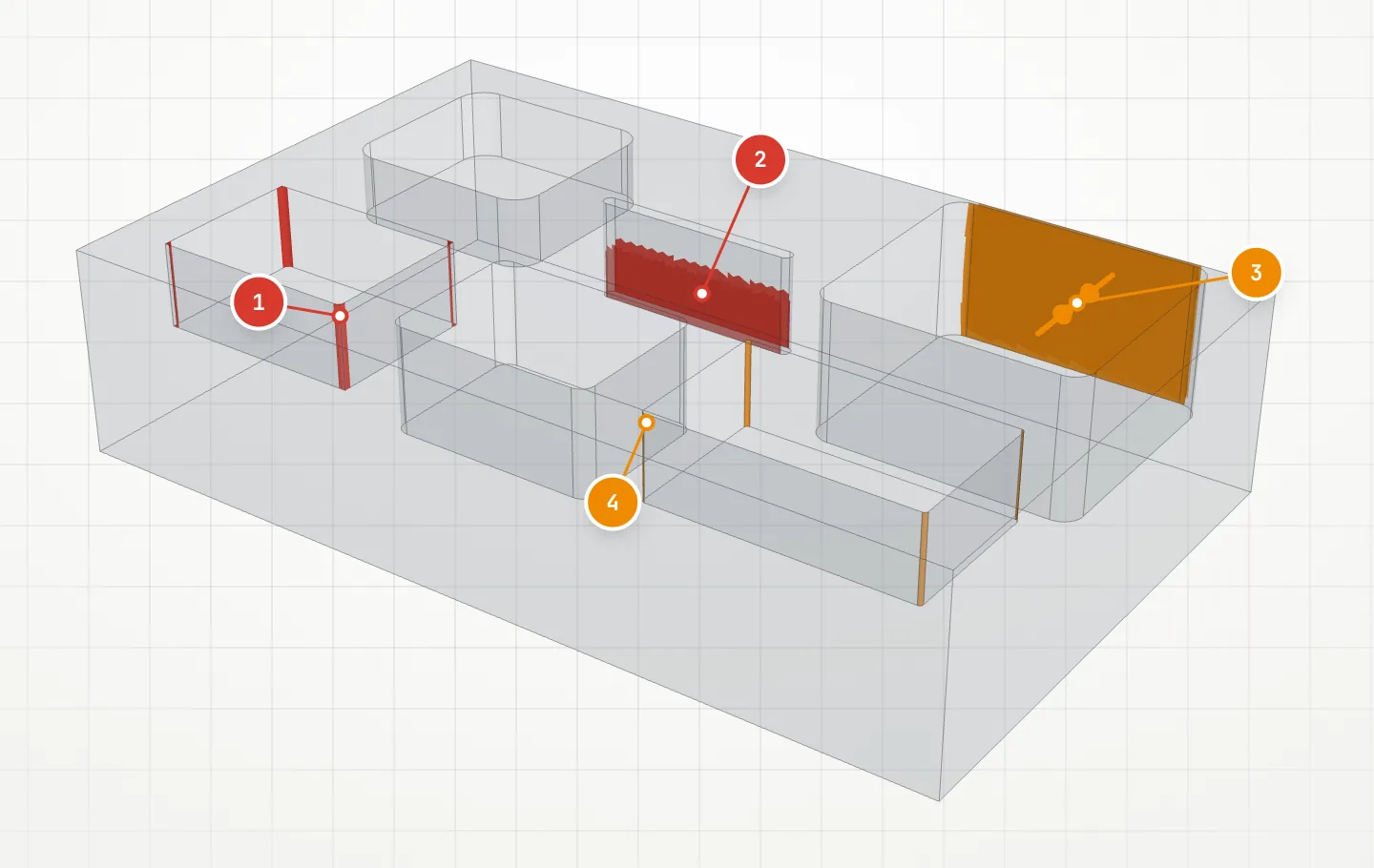
For CNC-machined parts. Upload the STEP and we check internal radii, walls, holes, slots and areas with no access. In red, what can't be made as drawn; in orange, what makes the part more expensive. Free, no sign-up.

Check manufacturability
Manufacturability check of a sample part: in red, what can't be machined as drawn; in orange, what makes the part more expensive

03 / Choose process and material

Before you quote,
decide with data.

Two tools: one tells you which process to start with and the other puts materials side by side.

CNC · 3D printing · sheet metal · casting

Process selector

Material
Part type
Units
First choiceCNC machining

Housings with pockets and seats, in the final material.

Open the full selector
33 materials · side by side

Material comparison

Density2.71 g/cm³1.41–1.43 g/cm³
Made withCNC · Sheet metalCNC
StrengthsElectrical conductor · Corrosion resistant · Withstands temperatureWear resistant · Chemical resistant · Electrical insulator
Compare in detail

04 / ISO 286 calculators

Tolerances and fits,
calculated instantly.

Try it here. Complete table, diagrams, and all classes, in each calculator.

A part · hole or shaft

Tolerance calculator

HoleØ25 H7
Maximum size25,021mm+21 µm
Minimum size25,000mm0 µm
Open full calculator
Hole + shaft

Fit Calculator

ClearanceØ25 H7/g6
Minimum clearance+7µm
Maximum clearance+41µm
Open full calculator

05 / Design guides

The cost of a part
is decided in the design.

The rules we apply in the workshop after thousands of prototypes. Free, in PDF.

In this guide
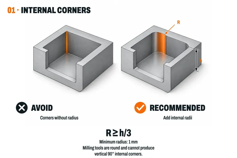
  1. How your part is machined
  2. Tolerances: how much to ask for
  3. The seven rules
  4. Materials and finishes
  5. Cost: splitting the part and lowering the price
  6. Summary and checklist
Proto&Go! · Design guide
Cover of the CNC machining design guide

Milling and turning

Design guide for CNC machining

In this guide
  1. How your part is printed
  2. PA12 or TPA
  3. Size and tolerances
  4. The six rules
  5. Redesign, finish and assembly
  6. Summary and checklist
Proto&Go! · Design guide
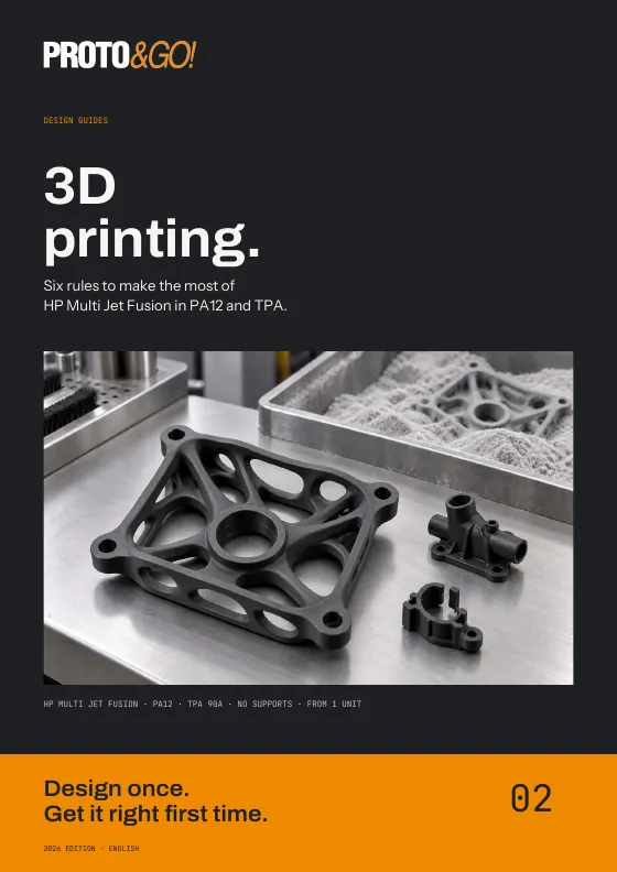
Cover of the 3D printing design guide

HP Multi Jet Fusion

Design guide for 3D printing

In this guide
  1. How your part is made
  2. We calculate the flat pattern
  3. The six rules
  4. Tolerances, materials and finishes
  5. Stiffness, assembly and file
  6. Summary and checklist
Proto&Go! · Design guide
Cover of the sheet metal cutting and bending design guide

Laser cutting and CNC bending

Design guide for sheet metal cutting and bending

In this guide
  1. How your short run is made
  2. Which polyurethane
  3. Tolerances and fit
  4. The five rules
  5. Master, color, and quantity
  6. Summary and checklist
Proto&Go! · Design guide
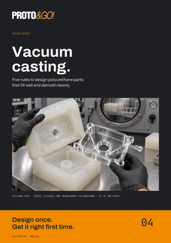
Cover of the vacuum casting design guide

Polyurethane in silicone mold

Design guide for vacuum casting

English guide

Design guide for CNC machining

Protected against automated submissions by Cloudflare Turnstile. Privacy.

06 / Accepted files

Is your file suitable?
Check it.

A 3D model per part. The PDF, only as a drawing for reference.

Drop your file here
.STEPAccepted

Neutral format recommended for any process.

Open it in the 3D viewer
  • CNC machining
  • 3D printing
  • Silicone molds
  • Sheet metal

07 / Frequently asked questions

Technical queries,
solved.

38 questions

What tolerance does a machined part have if I do not specify any?

If you do not specify tolerances, Proto&Go! applies the general ISO 2768-f tolerance for metals and ISO 2768-m for plastics. For a 25 mm dimension in metal, that means ±0.10 mm, the thickness of two sheets. This is sufficient for most functional parts, housings, supports, and prototypes.

Why does a tight tolerance increase the cost of a CNC part?

A tighter tolerance than the general one requires slower finishing passes, more careful measurement, and more rejected parts. That is why it is best reserved for dimensions that truly need it, such as a bearing housing. For the rest, the general tolerance is already very fine and keeps the price low.

What maximum precision is achieved with CNC machining?

For specific functional dimensions, Proto&Go! can reach an IT7 quality in metals, about 21 microns for a 25 mm dimension, and IT11 for plastics. Plastics expand and absorb moisture, so it is not advisable to demand metal-level precision. If a part needs such a fit, mention it to the engineering team when requesting the quote.

What surface roughness does CNC machining leave?

A machined part shows fine tool marks. At Proto&Go!, surfaces up to Ra 1.6 µm are achieved, about forty times finer than a hair. If you are looking for a uniform appearance, sandblasting or anodizing masks the marks.

What does H7 mean for a hole and what are its limit dimensions?

H7 defines the size tolerance of a hole. The letter H fixes the lower deviation at zero: the minimum size matches the nominal. The grade 7 determines the tolerance range according to the diameter. For example, a Ø25 H7 hole accepts sizes between 25.000 and 25.021 mm.

What is the difference between H7 for a hole and h6 for a shaft?

Uppercase letters identify hole tolerances and lowercase letters identify shafts. In H7, the hole can be equal to or larger than the nominal size; in h6, the shaft can be equal to or smaller. For the same nominal diameter, the H7/h6 combination has a minimum clearance of zero. Grades 7 and 6 determine the range of each tolerance.

How do I calculate the maximum and minimum dimensions of a shaft or hole according to ISO 286?

In the Proto&Go! tolerance calculator, select shaft or hole and enter the nominal size, position, and tolerance grade. You will obtain the maximum and minimum sizes in millimeters and the deviations in microns. The table allows comparing the available grades for that position. The tool covers nominal sizes greater than zero up to 500 mm.

What does the H7/g6 fit mean and how much clearance does it have for a 25 mm diameter?

H7/g6 is a clearance fit: the g6 shaft is smaller than the H7 hole for the same nominal diameter. At Ø25 mm, the diametral clearance ranges from 7 to 41 µm, that is, from 0.007 to 0.041 mm. For another diameter, recalculate the limits of both parts.

What is the difference between a clearance fit, an interference fit, and a transition fit?

In a clearance fit, the hole is equal to or larger than the shaft. In an interference fit, the shaft is equal to or larger than the hole, and assembly may require pressure or a temperature difference. In a transition fit, clearance or interference may occur depending on the actual measurements. Parts with the same nominal size are always compared.

What is the hole-basis system and how is the shaft fit selected?

In the hole-basis system, a hole with H tolerance position is maintained, and the shaft tolerance is selected to obtain the required fit. For example, H7/g6 provides clearance, H7/k6 may provide clearance or interference, and H7/p6 provides interference for a nominal diameter of 25 mm. The choice depends on how the joint must function and be assembled.

What is the ISO 2768 standard and how is it used on a drawing?

ISO 2768 sets general tolerances for dimensions that do not have a specified tolerance. Part 1 covers linear and angular measurements with four classes: f (fine), m (medium), c (coarse), and v (very coarse). Part 2 covers general geometric tolerances with classes H, K, and L. Thus, the drawing only needs explicit tolerances on functional dimensions.

What is the difference between ISO 2768-f and ISO 2768-m?

Class f (fine) is tighter than class m (medium). For linear dimensions:

  • Over 6 up to 30 mm: ±0.1 mm in f and ±0.2 mm in m.
  • Over 30 up to 120 mm: ±0.15 mm in f and ±0.3 mm in m.
  • Over 120 up to 400 mm: ±0.2 mm in f and ±0.5 mm in m.

If you do not specify tolerances, Proto&Go! applies ISO 2768-f for machined metal parts and ISO 2768-m for plastic.

What tolerance does ISO 2768-m give for a 50 mm dimension?

±0.3 mm: the dimension can measure between 49.7 and 50.3 mm. For the same dimension, the fine class (f) allows ±0.15 mm and the coarse class (c), ±0.8 mm. All dimensions over 30 up to 120 mm share these values.

What does ISO 2768-mK mean on a drawing?

It combines the two parts of the standard: «m» is the medium class for linear and angular dimensions (ISO 2768-1) and «K» is the intermediate class for general geometric tolerances, such as straightness, flatness, perpendicularity, or symmetry (ISO 2768-2). It applies to all dimensions and geometries that do not have a specified tolerance.

What is an IT tolerance grade and what does IT7 mean?

ISO 286 IT grades define the tolerance width according to the nominal size, from IT01 to IT18: the lower the number, the tighter the tolerance. For a 25 mm dimension, IT7 is 21 µm; IT6, 13 µm; IT8, 33 µm, and IT11, 130 µm. In machining, Proto&Go! achieves IT7 for functional metal dimensions and IT11 for plastic.

What tolerance does an h6 shaft of 20 mm have?

An Ø20 h6 shaft allows measurements between 19.987 and 20.000 mm: upper deviation 0 and lower deviation −13 µm. The letter h fixes the maximum measurement at the nominal size and grade 6 provides a width of 13 µm for diameters over 18 up to 30 mm. You can calculate other measurements with the tolerance calculator.

What are the limit dimensions of a g6 shaft of 25 mm?

An Ø25 g6 shaft measures between 24.980 and 24.993 mm, with deviations of −20 and −7 µm. It always stays below the nominal size; therefore, with an H7 hole, it forms a clearance fit of 7 to 41 µm.

What tolerance does an H7 hole of 10 mm have?

An Ø10 H7 hole allows measurements between 10.000 and 10.015 mm. The letter H sets the minimum measurement at the nominal size and grade 7 provides a width of 15 µm for diameters over 6 up to 10 mm.

What is the difference between the h7 tolerance of a shaft and the H7 tolerance of a hole?

They have the same width but in opposite directions. An H7 hole can be equal to or greater than the nominal size; an h7 shaft, equal to or less than. For Ø25 mm, H7 ranges from 25.000 to 25.021 mm and h7, from 24.979 to 25.000 mm.

What fit is used to press-fit a bushing or a pin?

In the hole-basis system the usual starting point is H7/p6, a light interference fit for fixed bushings pressed in. For a permanent joint, pressed or shrink-fitted, H7/s6 gives more interference. At Ø25 mm, H7/p6 has an interference of 1 to 35 µm and H7/s6, of 14 to 48 µm. Check it for your diameter with the fit calculator.

What fit should be chosen for a shaft that rotates or slides inside a bushing?

For precise and smooth sliding, H7/g6 is typically used, with a clearance of 7 to 41 µm for Ø25 mm. For shafts rotating at medium speed with lubrication, H8/f7 allows more clearance: 20 to 74 µm for Ø25 mm. If the part only needs to be centered and removed by hand, H7/h6 has a minimum clearance of zero.

What fit is used to mount a bearing on the shaft and in the housing?

It depends on which ring rotates relative to the load, the size, and the bearing manufacturer. In the most common case, a rotating shaft with a rigid ball bearing and normal load, SKF, NTN, and Schaeffler recommend the shaft in k5 for diameters of about 18 to 100 mm; j6 or js6 for light loads, and m5 or m6 for larger diameters or high loads. The housing, with the outer ring fixed relative to the load, is usually H7; if the load changes direction, J7 or K7. Qualities 5 and 6 of the shaft usually require grinding. Confirm the fit in the manufacturer's catalog and indicate it on the part PDF drawing.

What is the difference between the shaft-basis system and the hole-basis system?

In the shaft-basis system, the shaft maintains position h, with the maximum size equal to the nominal, and the hole tolerance is changed to achieve clearance, transition, or interference. In the hole-basis system, the hole is fixed in H and the shaft is selected. The hole-basis system is the most common, because holes are manufactured and verified with fixed measuring tools and gauges, and it is simpler to vary the shaft.

What is the difference between a dimensional tolerance and a geometric tolerance?

Dimensional tolerance limits the size of a dimension, for example Ø25 H7 or 40 ±0.1 mm. Geometric tolerance limits the form, orientation, or position: flatness, cylindricity, perpendicularity, parallelism, or position of a drilled hole, according to ISO 1101. Proto&Go! calculators solve dimensional tolerances; geometric tolerances are indicated on the part PDF drawing.

How do I request a tighter tolerance than the general one for a part?

Attach a PDF drawing assigned to the part and mark only the dimensions that need it, with their tolerance, for example Ø12 H7 or 30 ±0.02 mm. The rest of the dimensions are machined with the general tolerance. Reserving tight tolerances for functional dimensions avoids increasing the part cost.

What tolerance do polyurethane parts made in silicone molds have?

The standard tolerance for vacuum casting is ±0.3 mm for dimensions up to 100 mm and ±0.3 % for larger dimensions. Polyurethane shrinks by approximately 0.15 %, and precision also depends on the master, the silicone mold, the polyurethane resin, and the geometry: thick walls and long, flat parts warp more. If a dimension requires higher precision, indicate it in the PDF drawing, and the engineering team will confirm feasibility when preparing the quote.

How much is a micron and how does it compare to a sheet of paper or a hair?

A micron (µm) is one-thousandth of a millimeter: 0.001 mm. A sheet of paper measures about 100 µm in thickness, and a hair, about 70 µm. Therefore, an IT7 tolerance of 21 µm on a 25 mm diameter is less than one-third the thickness of a hair.

Is the Proto&Go! ISO 286 tolerance calculator free?

Yes. The tolerance calculator and the fit calculator are free and do not require registration. They cover shafts and holes with nominal sizes greater than 0 up to 500 mm, including ISO 286-1 positions and qualities.

Where can I download a free CNC machining design guide?

On the Proto&Go! resources page you can download the CNC machining design guide as a free PDF, in Spanish, English, French or Italian. It explains how the part is machined, how much tolerance to ask for, seven illustrated rules (inside radii, walls, drilled holes, threads, slots, undercuts and through holes), materials and finishes, and how to lower the cost.

What does the Proto&Go! 3D printing design guide include?

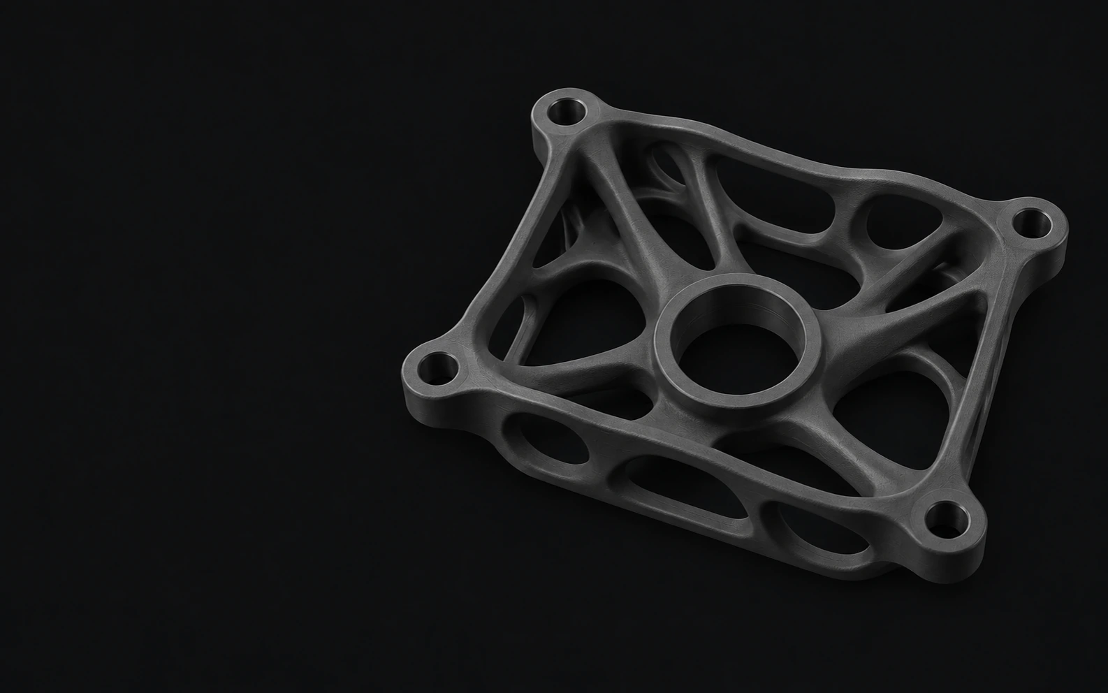
The free PDF guide explains how an HP Multi Jet Fusion printer works, when to choose PA12 or TPA, size and tolerances, six illustrated rules (wall thickness, hollowing, holes, printed threads, inserts and text) and how to redesign, finish and assemble the part. You can download it in Spanish, English, French or Italian on the Proto&Go! resources page.

Is there a design guide for sheet metal cutting and bending?

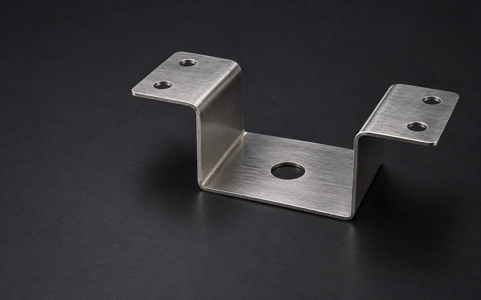
Yes. On the Proto&Go! resources page you can download the design guide for sheet metal cutting and bending as a free PDF, in Spanish, English, French or Italian. It explains how the part is laser-cut and bent from your 3D model, six illustrated rules (inside radius, minimum flange, holes near the bend, hole diameter, bend reliefs and fasteners), tolerances, materials and finishes, and which file to send.

What does the vacuum casting design guide include?

The free PDF guide explains how the master and the silicone mold are made, which polyurethane to choose (rigid, flexible or transparent), tolerances, five illustrated rules (wall thickness, uniform thickness, ribs, undercuts and demolding, inserts and threads), color and finish, and how many parts each mold yields. You can download it in Spanish, English, French or Italian on the Proto&Go! resources page.

What file formats does Proto&Go! accept to manufacture a part?

Proto&Go! accepts one 3D model per part in STEP (.stp, .step), SLDPRT, X_T, X_B, IPT, CATPART, PRT, SAT, or 3DM. STL files are accepted only for 3D printing. A 2D file does not replace the 3D model; you can attach a PDF to indicate threads, inserts, tolerances, or other requirements.

Can I send an STL file to 3D print or machine a part?

At Proto&Go! you can send an STL for 3D printing. For CNC machining, silicone molds, or sheet metal, send STEP or one of the supported native formats. STL represents the surface via triangles; for those other processes, export the original model from your CAD software.

Why is it recommended to send the 3D model in STEP format?

STEP (.stp, .step) is a neutral format that preserves the exact geometry of the part and opens in any CAD software. That is why it is the safest option to quote and manufacture via CNC machining, silicone molds, or sheet metal. If you work with SolidWorks, Inventor, CATIA, Creo, NX, or Rhino, you can also upload the native file.

Does Proto&Go! accept IGES or DXF files?

No. Export the 3D model to STEP or upload a supported native format: SLDPRT, X_T, X_B, IPT, CATPART, PRT, SAT, or 3DM. A 2D drawing in DXF is also not suitable for sheet metal: the part is uploaded already bent in 3D and the development is calculated from the model.

Can I upload a complete assembly to request a quote?

No. Each file must contain a single part. If your design is an assembly, export each part you want to manufacture to an independent file and upload them separately, without screws or commercial elements. If the parts must fit together, indicate the fit dimensions in a PDF drawing.

When do I need to attach a PDF drawing to my 3D file?

Attach a PDF drawing assigned to the part when there is information not shown by the 3D model: threads and their metric, inserts, welds, or tolerances tighter than the general tolerance. If there are no special requirements, the 3D model is sufficient and the general tolerance applies.

Design ready?

Upload your file
and get a quote.

Upload your 3D model to the Proto&Go! platform, choose process, material, finish, and quantity. You'll receive the quote in 24 hours.

Upload your 3D file to the platform

It opens in a new tab. Accepted formats:

STEPSLDPRTX_T / X_BIPTCATPARTPRTSAT3DMSTL (only 3D printing)PDF (drawing)
Get a quote on the platform