STEP file: what it is and how to prepare it for a quote
STEP file: what it is, why machine shops prefer it to STL and how to export it properly. A 5-point checklist before uploading your part for a quote.
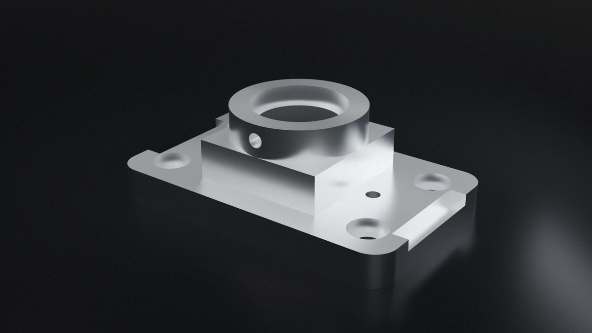
A STEP file is the standard 3D format for moving a part from one CAD program to another. It stores the exact solid, with its faces, edges and cylinders, and it is the file a shop needs to quote and manufacture your part. If you are ordering a CNC machined or 3D printed part, a properly exported STEP file is the shortest route to the quote.
Almost everyone knows how to export one. The hard part is exporting it properly: a single part, in millimetres, closed, and with a drawing when needed. In this article we look at what the STEP format is exactly, how it differs from an STL file and what to check before uploading it.
What a STEP file is and why the shop prefers it
STEP stands for Standard for the Exchange of Product model data and is the ISO 10303 standard. The .step and .stp extensions are exactly the same thing: the file name changes, not what is inside.
What matters is what it stores. A STEP file describes the part as an exact solid: a Ø8 hole is a Ø8 cylinder, a flat face is a plane and a radius is an arc. An STL file, on the other hand, is a triangle mesh that approximates the shape. That same hole becomes a polygon with many sides, and its diameter depends on where you measure it.
For the shop, that makes all the difference. The programmer works in the CAM software directly on the faces of the solid: they select a hole, a pocket or a contour and assign the tool to it. A mesh has no faces to select. In addition, a STEP file carries the units inside the file, so nobody has to guess whether the part measures 40 mm or 40 inches.
You will see that programs offer several versions when exporting: AP203, AP214 or AP242. All three are fine for manufacturing. If in doubt, choose AP214 or AP242: both store the geometry and the colours.
STEP, STL or native format: which file to send
The short answer: send STEP. Any CAD program can open it, it does not depend on your CAD version and it works for every process. Even so, the platform also accepts the most common native formats:
| Format | Extension | What it stores | Process |
|---|---|---|---|
| STEP | .step · .stp | Exact solid, neutral format | All: CNC, 3D printing, vacuum casting and sheet metal |
| Parasolid | .x_t · .x_b | Exact solid (kernel of SolidWorks, NX and Onshape) | All |
| SolidWorks | .sldprt | Native solid | All |
| Inventor | .ipt | Native solid | All |
| CATIA | .catpart | Native solid | All |
| Creo / NX | .prt | Native solid | All |
| ACIS | .sat | Exact solid, neutral format | All |
| Rhino | .3dm | Solid or NURBS surfaces | All, if it is a closed solid |
| STL | .stl | Triangle mesh | 3D printing only |
| Drawing | Threads, tolerances, inserts | Goes with the 3D model, never replaces it |
Two formats that often arrive and are not on the list: OBJ, which is another mesh and is best converted to STEP or STL, and IGES, an older format that usually arrives as loose surfaces instead of a solid. In both cases, export again in STEP from the original model.
Can you convert an STL file to STEP?
Yes, in a few clicks: FreeCAD, Fusion and many free converters can do it. The problem is the result. When you convert STL to STEP, most converters turn each triangle of the mesh into a flat face: the file changes extension, but it is still a mesh. Some, such as the Prismatic method in Fusion, try to recover planes and cylinders on simple parts, but the dimensions are still those of the mesh, not those of the original design.
In practice, with a direct conversion:
- Thousands of flat faces where there used to be a cylinder. A Ø10 hole is still a polygon.
- There is no geometry to select in the CAM software, so the part cannot be programmed like a normal machining job.
- The dimensions are approximate. Accuracy depends on how many triangles the original STL had.
- Very heavy files for a simple part.
For 3D printing this is not a problem: the STL as it is will do, with no need to convert it. For machining, the solution is to go back to the original model and export from it. If the model no longer exists and all you have is the STL or a drawing, the part has to be modelled again in a solid CAD program. Tell us when you request the quote and we will find the best way to do it.
How to export a STEP file from your CAD program
In every program it is under Save As or Export. Before you click, make sure you have the part open, not the assembly:
- SolidWorks. File › Save As, and in the file type choose STEP AP214 (*.step).
- Inventor. File › Save As › Save Copy As, and choose STEP Files (*.stp). In Options, choose the AP214 or AP242 protocol.
- Autodesk Fusion. File › Export › STEP. If the design has several bodies, export each part to its own file.
- Onshape. Right-click the part in the Parts list › Export, with STEP as the format. This exports only that part and not the whole Part Studio.
If you export from an assembly, the STEP file will contain all the parts together, including the fasteners. Open it part by part and export each one separately. The steps for CATIA, Creo, Solid Edge, FreeCAD and Rhino are on the STEP viewer page.
Before uploading it: five checks that save a round trip
A badly prepared file does not stop you from requesting a quote, but it delays it: someone has to write to you, wait for your reply and start again. Go through this list before uploading:
- One part per file. No screws, no off-the-shelf components and none of the rest of the assembly. If you are ordering an assembly, upload one STEP file per part and give each file a name that identifies it.
- Units in millimetres. If the part comes out 25.4 times bigger or smaller, it was exported in inches. This rarely happens with STEP because the units are inside the file, but it is worth checking.
- Closed solid. If a face is missing, the part has no volume and the program does not know where the material is. This usually happens when converting from another format or when exporting surfaces instead of solids.
- 100 MB maximum. A STEP file of a normal part takes up a few megabytes. If it is much heavier, it usually carries detail that is not needed for manufacturing, such as threads modelled turn by turn, embossed text or knurling.
- A PDF drawing if there are threads, tolerances or inserts. The 3D model does not say which hole is threaded, which dimension needs a specific tolerance or where an insert goes. That goes in a simple drawing, even if it only dimensions those points.
How to check your STEP file for free before sending it
You do not need to have your CAD at hand. Drag the file into the STEP viewer and within seconds you will have the part in 3D, with no sign-up and without the file being saved. Look at three things:
- The bounding box. If the dimensions do not match your part, there is a units problem.
- The number of solids. If there is more than one, the file contains several parts.
- The volume. If it is not calculated, the solid is not closed.
If the part is for machining, also click Check manufacturability. The manufacturability analysis marks in red what cannot be machined and in orange what makes it more expensive, such as an internal radius that is too small. The viewer accepts STEP files of up to 10 MB; if yours is larger, upload it directly to the platform.
We check every file before preparing the quote. If we receive a mesh, several parts together or a thread without a drawing, we tell you and suggest a solution. The quote, in 24 hours.
More details on how the platform works and on the most common mistakes when ordering a prototype.
Request your quote with PROTO&GO!
With the STEP file ready, the rest is quick. At PROTO&GO! you upload the file, choose the process, material, finish and up to three quantities, and you get the quote in 24 hours with the engineering review included. We manufacture from a single unit by CNC machining, 3D printing and vacuum casting.
Upload your STEP file and clear up any doubts about your part.